
Welcome To Metrioc Force Measurement & Calibration

ASTM E74 & ISO 376

Load Cell Calibration: A Complete Guide to Accuracy, Traceability, ASTM E74, and Best Practices

Ali Zeinali, PhD Ali Zeinali, PhD 16 min read
Load Cell Calibration: A Complete Guide to Accuracy, Traceability, ASTM E74, and Best Practices

Load Cell Calibration Best Practices

This guide explains load cell calibration best practices for achieving accurate, traceable results, including ASTM E74 requirements, proper procedures, documentation, and recalibration intervals.

What Is Load Cell Calibration?

Load cell calibration is the process of applying accurately known forces to a load cell and comparing those forces with the electrical or digital output produced by the measurement system. The result establishes a documented relationship between applied force and the reading produced by the load cell, indicator, amplifier, or data-acquisition system.

A load cell may be manufactured from excellent materials and have impressive published specifications. However, those specifications do not establish the exact response of an individual device in its actual measurement system.

Calibration determines how that specific load cell behaves when force is applied. A proper calibration establishes the output-to-force response, repeatability, orientation effects, measurement uncertainty, verified range, and required conversion equation.

These factors become especially important when a load cell serves as a reference force standard or supports testing-machine calibration.

What Is a Load Cell?

A load cell is a force-measuring transducer. It converts tension, compression, or another applied mechanical force into an electrical output that can be measured, displayed, recorded, or used by a control system.

Load cells are used in testing machines, structural and material testing, thrust measurement, weighing systems, industrial monitoring, calibration laboratories, and field verification.

Two important categories are strain gauge load cells and piezoelectric load cells.
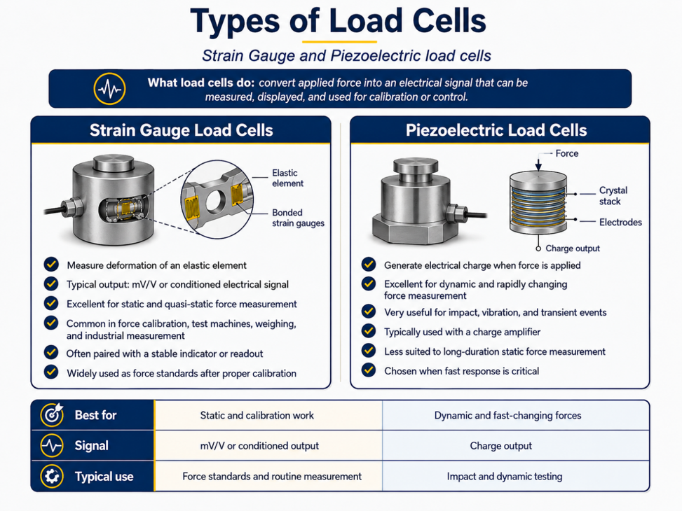
Comparison of strain gauge and piezoelectric load cells for static and dynamic force measurement.

Strain Gauge Load Cells

Strain gauge load cells are the most common type used for static and quasi-static force measurement. They are also widely used as force standards after proper calibration.

A strain gauge load cell contains a carefully designed elastic metal flexure element. When force is applied, the element deforms by a very small amount. Bonded strain gauges detect this deformation through changes in electrical resistance.

The gauges are commonly arranged in a Wheatstone bridge circuit. As the elastic element deforms, the bridge produces an electrical signal related to the applied force.

For an unamplified load cell, output is often expressed in millivolts per volt, or mV/V. This describes the ratio between output voltage and excitation voltage.

A nominal value on a data sheet does not represent the exact calibrated response of an individual load cell. Therefore, a reliable statement about a load cell’s output signal requires a proper calibration procedure.

Strain gauge load cells are well suited for static force, compression and tension calibration, testing-machine verification, industrial measurement, and use as transfer or field force standards.

Their performance also depends on the cable, indicator, excitation source, adapters, alignment, environment, and loading procedure.

Piezoelectric Load Cells

Piezoelectric load cells use quartz or engineered piezoelectric materials that generate electrical charge when mechanical force is applied.

The charge is collected through electrodes and converted into a usable signal by a charge amplifier or integrated electronic circuit.

Piezoelectric sensors respond quickly, making them useful for impact, vibration, transient events, and other dynamic measurements. However, they are less suitable for long-duration constant force because the signal gradually decays.

For this reason, strain gauge load cells are more common as static force standards.

Why Is Load Cell Calibration Necessary?

The output of a load cell is an electronic signal that does not inherently provide measurement information in force units. Calibration translates that electronic signal into an actual force value.

In other words, calibration establishes the actual performance of a load cell rather than relying only on nominal specifications.

Moreover, a load cell’s technical specification typically states an approximate signal level at the capacity load. A proper calibration establishes performance across the load cell’s operating range.

Real Sensitivity

The rated output on a data sheet is normally a nominal value. Actual response may vary because of manufacturing tolerances, material behavior, strain gauge installation, wiring resistance, excitation voltage, and signal conditioning.

Calibration measures the response of the specific load cell system.

Nonlinearity

A load cell may not respond in a perfectly straight line over its full capacity. Even small nonlinearity can matter when high accuracy is required.

Therefore, calibration allows the laboratory to establish an equation that represents the measured relationship between output and force more accurately than a simple linear assumption.

Repeatability and Orientation

Repeatability describes how closely repeated measurements agree under similar conditions.

A load cell may also respond slightly differently when rotated around its primary axis because of internal construction, cable location, machining, mounting, or adapter interaction.

Multiple calibration series and rotational positions help evaluate these effects.

Traceability

Traceability connects a result to recognized measurement standards through a documented chain of calibrations.

For force measurements, that chain ultimately connects the result to the SI unit of force, the newton.

NIST traceable load cell calibration requires a documented chain connecting the measurement result to recognized standards through appropriate reference standards and calibration procedures.

A credible traceability statement requires more than the phrase “NIST traceable.” It requires suitable reference standards, documented calibration links, measurement uncertainty, valid procedures, and correct use of the calibration result.

Measurement Uncertainty

No measurement is perfectly exact. Measurement uncertainty expresses the range of values that can reasonably be associated with a result.

A load cell calibration uncertainty may include the effects of the reference standard, repeatability, resolution, zero return, rotation, temperature, alignment, force stability, excitation stability, data fitting, and fixtures.

Without an uncertainty statement, the user has an incomplete picture of measurement quality.

Why an Expensive Load Cell Is Not Enough

A higher-priced load cell may offer better materials, lower nominal nonlinearity, improved sealing, higher fatigue resistance, or better temperature compensation.

These features can be valuable, but they do not replace calibration.

Without calibration, the user may not know the actual sensitivity, repeatability, orientation effect, influence of the cable and indicator, correct conversion equation, verified force range, or measurement uncertainty.

A lower-cost load cell with a high-quality calibration, stable instrumentation, proper adapters, and controlled use may produce more defensible results than an expensive load cell used with an assumed sensitivity and poor setup.

Therefore, the better question is not simply, “How accurate is this load cell?”

It is:

What is the measurement uncertainty of this complete load cell system when calibrated and used in its intended configuration?

What Is Involved in Load Cell Calibration?

High-quality load cell calibration requires mechanical preparation, controlled force application, electrical stability, and careful data analysis.

Review of the Intended Application

The laboratory should understand the loading direction, capacity, minimum force, intended use, required procedure, field cable and indicator, adapters, and whether decreasing-force data are needed.

This information determines the machine, standards, fixtures, sequence, and analysis method.

Inspection

Before high forces are applied, the laboratory should inspect the load cell, cable, connectors, threads, surfaces, adapters, and indicator for damage, corrosion, overload evidence, contamination, or mismatched accessories.

Reference Force Standard

The applied force must be generated or measured using appropriate standards with suitable traceability and uncertainty.

Depending on the range, a laboratory may use deadweight machines, hydraulic transfer force-standard machines, lever systems, build-up systems, reference load cells, or force comparison machines.

Adapters and Alignment

Adapters transfer force from the calibration machine into the load cell.

Examples include compression pads, thrust blocks, spherical seats, ball adapters, tension rods, clevises, threaded adapters, and custom fixtures.

They must have adequate capacity, stiffness, contact area, and thread engagement. They should also apply force along the intended axis without excessive side load, bending, torsion, or eccentricity.

Poor alignment can create bending moments, edge loading, reduced repeatability, and differences between laboratory and field performance.

Stabilization and Preloading

The load cell should reach laboratory temperature, and the indicator or amplifier should receive adequate warm-up.

The laboratory should verify excitation voltage, zero balance, units, filters, and averaging settings.

In addition, preloading seats mechanical interfaces and reduces effects caused by initial settling, thread movement, surface seating, adapter repositioning, and load-train compliance.

Multiple Calibration Series

A meaningful calibration uses several force applications.

For example, the laboratory may apply ascending (increasing) force, return to zero, rotate the load cell, and repeat the sequence. Decreasing-force data may also be collected.

These multiple series reveal repeatability, rotational effects, zero behavior, and loading-history effects.

Data Analysis

After measurement, the laboratory evaluates repeated readings, fits the required equation, calculates residuals, determines uncertainty, establishes verified force ranges, and may compare the current results with previous calibrations.

Electrical and Technical Factors

Mechanical loading is only part of the calibration. Electrical configuration can also affect the result.

Important factors include excitation voltage, four-wire or six-wire connection, cable resistance, remote sensing, shielding, grounding, connector condition, electrical noise, indicator resolution, filtering, amplifier gain, sampling rate, zero and tare settings, unit conversion, and software calculations.

When a load cell is calibrated with one indicator and later used with another, the field result may no longer represent the calibrated system.

For field force standards, calibrating the load cell with the same cable and indicator used in service is often the strongest approach.

ASTM E74 Load Cell Calibration

The current standard title is: ASTM E74-18(2026), Standard Practices for Calibration and Verification for Force-Measuring Instruments.

ASTM E74 provides practices for calibrating static force-measuring instruments, including elastic instruments such as load cells and proving rings.

It is especially important when a load cell will be used as a force standard.

An ASTM E74 calibration may report:

  • Applied forces and load cell outputs
  • Multiple calibration series
  • Polynomial coefficients
  • Residuals from the fitted equation
  • Measurement uncertainty
  • Lower force limits
  • Verified Class A range
  • Verified Class AA range, when applicable
  • Load cell, cable, and indicator identification
  • Calibration direction and orientation
  • Environmental and traceability information

ASTM E74 is intended for static force calibration. Its results should not automatically be treated as a dynamic or high-speed calibration.

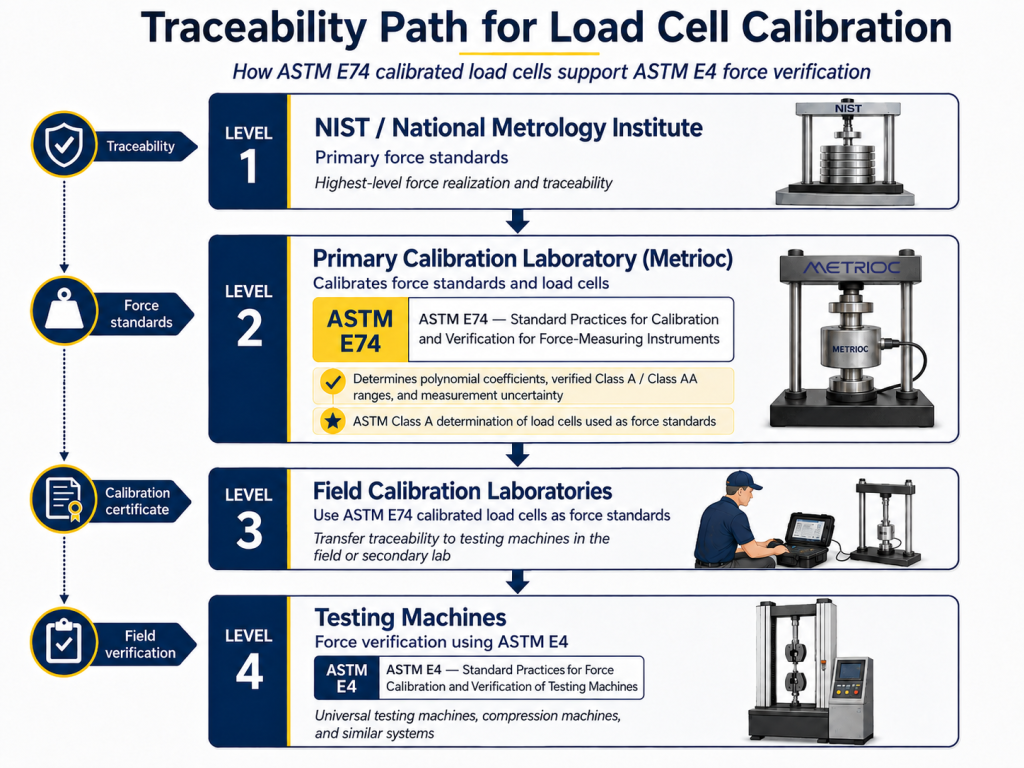
The Force-Measurement Traceability Chain

Force calibration traceability chain from national standards through ASTM E74 load cells to ASTM E4 testing-machine verification.

A typical force traceability chain has several levels.

At the highest national level, organizations such as NIST maintain force standards. A high-level calibration laboratory uses traceable reference standards, applies known forces to a customer’s load cell, and performs an ASTM E74 calibration when required.

The calibrated load cell may then serve as a transfer or field force standard within its verified range.

Field laboratories use these calibrated systems to transfer traceability to equipment such as universal testing machines, concrete compression machines, structural test frames, hydraulic presses, and material testing systems.

The current testing-machine standard title is: ASTM E4-24, Standard Practices for Force Calibration and Verification of Testing Machines.

ASTM E4 covers force calibration and verification of static or quasi-static tension and compression testing machines using suitable force standards.

The practical chain is:

National force standards → Primary force calibration laboratory → ASTM E74-calibrated load cell → field calibration laboratory → ASTM E4 testing-machine verification

Every level matters. A weakness in one step can affect the final force measurement.
ASTM E74 Class A and Class AA Ranges

An ASTM E74 calibration may establish a verified Class A range, a verified Class AA range, or both.

These classifications do not automatically apply to the entire capacity of the load cell. A verified range begins at a calculated lower force limit and extends to the applicable maximum calibrated force.

Below the lower limit, the load cell does not carry that class designation, even if it still produces readings.

Class AA represents a more demanding level than Class A.

A load cell may therefore have a Class AA range over the upper portion of its capacity, a Class A range beginning at a lower force, and no verified class below the applicable lower limit.

The exact ranges must be taken from the calibration certificate. They should never be assumed from rated capacity or a manufacturer’s specification.

Why the ASTM E74 Polynomial Equation Matters

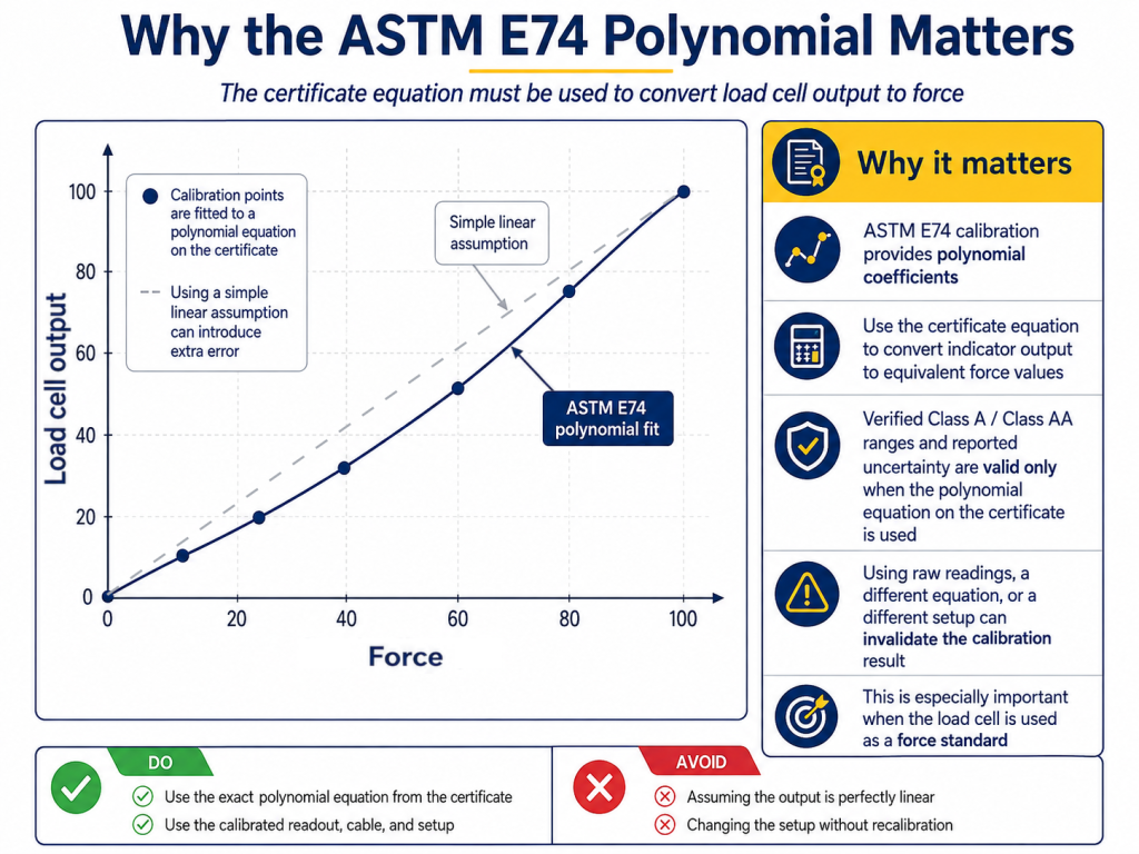
ASTM E74 polynomial calibration curve converting load cell output into equivalent force values.

A load cell does not necessarily produce an output that is perfectly proportional to force.

Even small deviations from a straight line can matter when the load cell is used as a reference standard.

ASTM E74 calibration data is fitted to an equation that represents the relationship between output and force.

A simplified example is:

Force = A₀ + A₁R + A₂R² + A₃R³

Here, R is the load cell or indicator reading, while A₀, A₁, A₂, and A₃ are calibration coefficients.

The exact equation and coefficient order must be taken directly from the certificate.

The coefficients are not optional supporting information. They are part of the calibrated conversion from output into equivalent force.

Using only a nominal sensitivity, a single span factor, or an assumed straight line can produce a different result.

Most importantly:

The verified Class A range, verified Class AA range, and associated uncertainty are valid only when the polynomial equation on the certificate is correctly used to convert output into force.

Indicator counts, volts, or mV/V readings are not automatically force values. They must be processed using the equation and instructions on the certificate.

Field software, spreadsheets, indicators, or data-acquisition systems must use the correct equation, coefficient order, input units, force units, sign convention, zero correction, and calibrated configuration.

A misplaced decimal point, reversed coefficient order, or incorrect unit conversion can invalidate the result.

Calibrate the Load Cell as a Complete System

A load cell does not operate alone.

The complete system may include the load cell, cable, indicator, amplifier, excitation source, connectors, data-acquisition hardware, software, adapters, and loading fixtures.

Whenever practical, a load cell intended for field calibration should be calibrated with the same cable and indicator that will be used in the field.
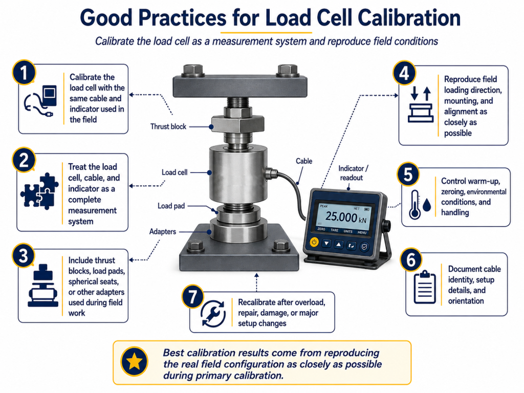
: Load cell calibration best practices showing the load cell, indicator, cable, thrust block, load pad, and adapters.


Why the Cable Matters

A cable can affect bridge excitation, voltage drop, resistance, remote sensing, shielding, electrical noise, and connector stability.

Replacing a calibrated cable with one of a different length, conductor size, wiring arrangement, or connector condition may change the system response.

Why the Indicator Matters

Indicators differ in excitation stability, sensitivity, resolution, linearity, filtering, digital conversion, internal scaling, and polynomial capability.

A load cell calibrated with one indicator should not automatically be expected to produce the same result with another.

The certificate should identify the load cell, cable, indicator, relevant software, connection, and units. This documentation helps prevent the calibrated system from being unknowingly reassembled with different components.

Reproduce Field Conditions During Calibration

Calibration results are most representative when the laboratory reproduces the real field configuration as closely as practical.

Thrust blocks and load pads affect contact geometry, alignment, stiffness, load distribution, and mechanical seating.

If they are used during field calibration of testing machines, including them in the primary calibration can make the result more representative.

Spherical seats, tension rods, clevises, pins, threaded adapters, and custom fixtures can also influence loading. Their inclusion should be considered when they are part of normal field use.

The laboratory should also match the loading direction.

A load cell calibrated in compression should not automatically be assumed to behave the same way in tension.

Whenever practical, reproduce the load cell orientation, cable exit direction, warm-up time, zeroing method, filter and averaging settings, force dwell time, loading rate, ascending or descending (increasing or decreasing) sequence, and relevant environmental conditions.

A correct laboratory calibration may still be poorly reproduced when the field setup is substantially different.

Common Load Cell Calibration Mistakes

Common mistakes include:

  • Using nominal rated output instead of calibration results
  • Ignoring ASTM E74 polynomial coefficients
  • Using a different indicator without evaluation
  • Replacing the cable without considering its effect
  • Calibrating without field adapters
  • Applying force with poor alignment
  • Using the load cell below its verified range
  • Confusing display resolution with accuracy
  • Treating “NIST traceable” as sufficient documentation
  • Applying a static calibration to dynamic force measurements

Recalibration and Certificate Review

The calibration interval should reflect usage, stability history, transportation, environment, uncertainty needs, and risk.

Recalibration should also be considered after overload, repair, cable or indicator replacement, major adapter changes, damage, unexpected zero shift, or failed intermediate checks.

A useful certificate should identify the calibrated system, procedure, force points, readings, polynomial equation, verified ranges, uncertainty, conditions, traceability, reference standards, calibration date, approval, and accreditation information.

Users should review the complete certificate rather than relying on a sticker or pass/fail statement.

Choosing a Load Cell Calibration Services

When comparing load cell calibration services, consider more than maximum capacity.

Look for:

  • ISO/IEC 17025-accredited calibration
  • ASTM E74 capability
  • Proper force standards that cover the entire calibration range classifications, with standards switched when needed
  • Class A and Class AA determination
  • Appropriate measurement uncertainty
  • Compression and tension calibration
  • Ascending and descending (increasing and decreasing) force data
  • Calibration with the customer’s indicator and cable
  • Calibration with field adapters
  • Polynomial coefficients
  • Clear technical support
  • Coverage of the required minimum and maximum force range

The laboratory should also understand the intended use.

For example, a load cell used as an ASTM E4 field force standard may require a more detailed calibration than a sensor used for routine process monitoring.

Calibration results are most representative when the laboratory reproduces the real field configuration as closely as practical.

Thrust blocks and load pads affect contact geometry, alignment, stiffness, load distribution, and mechanical seating.

If they are used during field calibration of testing machines, including them in the primary calibration can make the result more representative.

Spherical seats, tension rods, clevises, pins, threaded adapters, and custom fixtures can also influence loading. Their inclusion should be considered when they are part of normal field use.

The laboratory should also match the loading direction.

A load cell calibrated in compression should not automatically be assumed to behave the same way in tension.

Whenever practical, reproduce the load cell orientation, cable exit direction, warm-up time, zeroing method, filter and averaging settings, force dwell time, loading rate, ascending or descending (increasing or decreasing) sequence, and relevant environmental conditions.

A correct laboratory calibration may still be poorly reproduced when the field setup is substantially different.

Load Cell Calibration at Metrioc

Metrioc provides high-accuracy calibration for load cells, force transducers, crane scales, dynamometers, proving rings, load pins, wheel load scales, multi-axis sensors, and specialized assemblies.

The force standards used include deadweight systems and transfer standards calibrated directly by NIST to provide the highest levels of accuracy for each calibration.

Capabilities include ASTM E74 and ISO 376 calibration up to 1,000,000 lbf for applicable instruments.

Customers can define the complete configuration, including the load cell, cable, indicator, thrust block, load pad, tension adapters, and other field accessories.

This system-based approach makes the result more meaningful and reproducible in actual use.

Frequently Asked Questions

What Is Load Cell Calibration?

Load cell calibration compares a load cell system’s output with accurately known applied forces to establish the relationship between output and force.

What Is ASTM E74 Calibration?

ASTM E74 is a standardized practice for calibrating and evaluating static force-measuring instruments, especially load cells used as force standards.

What Is a Class A or Class AA Load Cell?

These classifications apply only over the verified ranges reported on the ASTM E74 certificate.

Class AA is more demanding than Class A and represents a range with higher accuracy.

Why Must the Polynomial Coefficients Be Used?

The polynomial coefficients represent the calibrated relationship between output and force.

The verified ranges and associated uncertainty depend on using the certificate equation correctly.

Should the Load Cell and Indicator Be Calibrated Together?

When the load cell and indicator will be used together in the field, calibrating the load cell, cable, and indicator as one system is generally a strong practice.

Should Field Adapters Be Included?

When practical, yes.

Including thrust blocks, load pads, spherical seats, and tension adapters can make the calibration more representative of actual use.

Can ASTM E74 Calibration Be Used for Dynamic Force?

ASTM E74 is intended for static force-measuring instruments.

Dynamic or high-speed applications may require another calibration approach.

Final Thoughts

Load cell calibration is more than checking whether a sensor produces a reasonable number.

It establishes a traceable, uncertainty-supported relationship between applied force and the output of a complete measurement system.

The load cell, cable, indicator, excitation source, software, adapters, alignment, environment, loading sequence, and mathematical equation can all affect the final result.

For load cells used as force standards, ASTM E74 calibration provides the polynomial coefficients, measurement uncertainty, and verified Class A or Class AA ranges needed for correct use.

Those results remain meaningful only when the user applies the certificate equation, stays within the verified range, uses the calibrated components, reproduces the intended setup, maintains proper alignment, controls field conditions, and recalibrates when the system changes.

An expensive load cell may be a well-built sensor, but without technically sound calibration and correct use of the certificate, it is not yet a dependable force standard.

Metrioc provides NIST-traceable load cell calibration with documented measurement traceability and uncertainty.

For high-accuracy load cell calibration, ASTM E74 calibration, or assistance reproducing a field measurement system, contact Metrioc.

Metrioc — The Standard Behind the Standards.

Ali Zeinali, PhD
Written by

Ali Zeinali, PhD