


Crane Scale Calibration: Why Shackles, Hooks, and Alignment Matter
Crane scales are designed to operate as part of a lifting system. In service, the instrument is rarely loaded as an isolated sensor. Force is transmitted through shackles, pins, hooks, swivels, clevises, and other hardware before it reaches the crane scale’s sensing element.
That mechanical load path matters during calibration.
A calibration laboratory may have a force standard with sufficient capacity to calibrate a crane scale, but force capacity alone does not guarantee that the calibration setup represents how the instrument is actually used. The way force is introduced into the scale—including shackle geometry, pin diameter, hook position, alignment, and freedom to rotate—can influence the loading condition experienced by the sensing element.
For that reason, good crane scale calibration should consider more than the number shown on the display. The mechanical configuration, environmental condition, electrical readiness, and intended application should all be evaluated when establishing an appropriate calibration setup.
This article examines the factors that can make crane scale calibration different from the calibration of a conventional load cell or force transducer.
What Makes Crane Scale Calibration Different?
A conventional force transducer may be installed between carefully machined fixtures with threaded connections or loading surfaces designed specifically for axial force calibration.
A crane scale usually has a more complex mechanical load path.
A typical assembly may include:
support → upper shackle → shackle pin → crane scale → lower swivel or connector → hook → suspended load
Every interface introduces geometry that can affect how force reaches the sensing element.
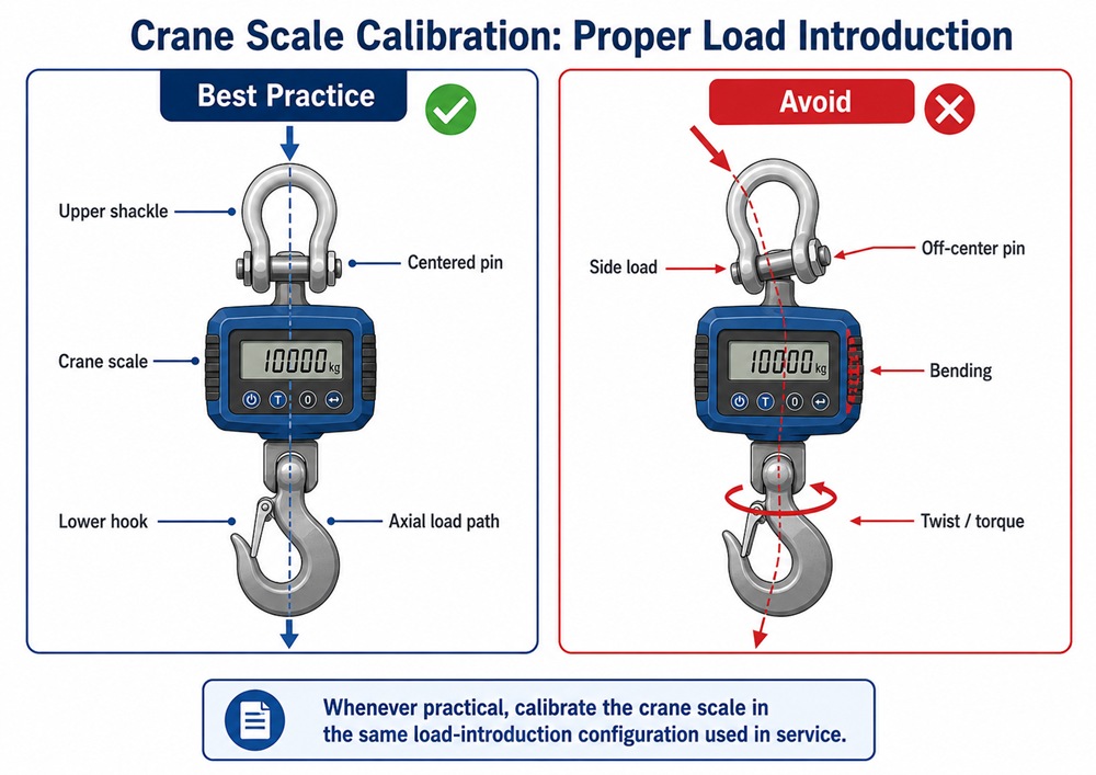
Ideally, the applied force acts along the intended measurement axis. In practice, however, a crane scale may experience some combination of:
- off-center loading,
- side loading,
- bending,
- torsion,
- variations in pin contact,
- rotation of the hook or shackle,
- and differences in how the hardware seats under load.
These effects are important because a force transducer is designed primarily to measure force along a particular axis. Unwanted components of force or moment can change the stress distribution within the transducer and, depending on the instrument design, may influence its indication.
The importance of alignment is well established in force metrology. ASTM E1012-19, although written for alignment verification of testing frames and specimens rather than specifically for crane scales, recognizes that bending stresses resulting from misalignment between the applied-force axis and the intended axis can affect measurement results.
For crane scales, the same underlying mechanical principle applies: the closer the calibration load path is to the intended axial load path, the more representative the loading condition is likely to be.
The Crane Scale Is Part of a Mechanical Load Train
It is tempting to think of the digital crane scale itself as the complete measuring instrument. Mechanically, however, its response is influenced by how force enters and leaves the sensing structure.
Consider the upper connection.
The suspended force may pass through a large shackle pin into an eye or load-bearing feature on the crane scale. The size of that pin, its location within the connection, and the ability of the assembly to center itself determine where contact occurs.
The lower connection may behave differently again. A hook can rotate or swing. A swivel may relieve torsion. A rigid adapter may not.
Consequently, changing the attachment hardware during calibration can change the mechanical boundary conditions of the instrument.
This does not mean that every small change in a shackle or fixture will produce a measurable calibration error. It means that the calibration laboratory should avoid unnecessarily changing the load-introduction condition when the customer’s normal configuration can reasonably be reproduced.
That principle becomes particularly important when high accuracy is required.
Why Hooks and Shackles Should Stay With the Scale When Practical
When a crane scale is normally operated with specific shackles, hooks, swivels, or related hardware, supplying that hardware with the instrument allows the calibration laboratory to reproduce the normal loading configuration more closely.
There are several advantages.
First, the actual components determine the physical location at which force enters the crane scale.
Second, they affect the amount of freedom the assembly has to rotate or self-align.
Third, they determine how contact occurs between pins and load-bearing surfaces.
Finally, including the normal hardware allows the laboratory to identify setup-related effects that could be missed if the scale were calibrated using completely different adapters.
Whenever practical, therefore, a crane scale should be calibrated using its normal load-introduction hardware or a representative configuration that closely reproduces it.
There are exceptions. Hardware may be unsuitable for use in a calibration machine, may require separate inspection, may not be supplied by the customer, or may create a safety concern. In those cases, properly designed calibration adapters may be necessary.
The important point is not that every crane scale must always be calibrated with every piece of lifting hardware attached.
The important point is that changing the hardware changes the mechanical setup, and that change should be understood rather than ignored.
When the Original Shackle Is Not Available: Why Pin Diameter Matters
One of the most easily overlooked details in crane scale calibration is pin diameter.
Suppose a crane scale is designed to operate with a manufacturer’s specified shackle and pin, but the customer removes the shackle before sending the unit for calibration.
The laboratory must then connect the scale to its calibration machine using another fixture.
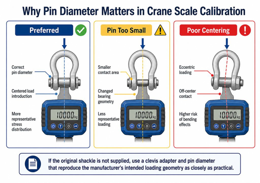
A common solution is a clevis-style adapter with a cross pin. That can be an effective approach—but the pin should not simply be selected because it happens to fit through the opening.
Pin diameter influences load introduction
Consider a crane scale connection designed around a relatively large pin.
Under tensile load, that pin bears against a portion of the scale’s eye, link, or other load-bearing feature. The pin diameter helps determine:
- the contact location,
- the bearing area,
- the curvature at the contact interface,
- and the path through which force enters the structure.
If the calibration laboratory substitutes a much smaller pin, the contact region can move and become more localized.
That changes the load-introduction geometry.
Depending on the design of the crane scale, the resulting stress distribution can be different from the distribution produced by the manufacturer’s intended pin.
A smaller pin may also allow greater freedom for the connection to shift away from its intended centered position.
The objective is therefore not simply to find a strong enough pin.
The objective is to reproduce the manufacturer’s intended loading geometry as closely as practical.
A practical calibration approach
If the original shackle is unavailable, a good approach is to review the crane scale manufacturer’s specifications and determine the recommended or original shackle pin diameter.
The calibration laboratory can then use a properly designed clevis adapter with a pin of the same nominal diameter—or a diameter that reproduces the intended loading condition as closely as practical.
The pin should also be properly centered and suitable for the applied force.
This is especially important for crane scales in which the sensing structure is located close to the attachment point, because changes in contact position can potentially have a greater influence on how strain is distributed through the instrument.
The purpose of matching pin geometry is not to claim that one arbitrary pin size will always produce an unacceptable error. Rather, it is to remove an unnecessary variable from the calibration setup.
When practical, calibrate the instrument under a loading geometry representative of its intended use.
Alignment: Keeping Force on the Measurement Axis
Alignment is one of the most important considerations in force measurement.
In an ideal tensile calibration, the force vector passes through the intended measurement axis of the crane scale.
If the upper and lower loading points are displaced from that axis, additional mechanical effects can be introduced.
These may include:
Side load
A lateral component of force acts across the transducer instead of purely along its intended axis.
Bending
If the applied-force line does not pass through the intended axis, a bending moment may develop.
Torsion
If the upper and lower attachments resist rotation or are twisted relative to one another, torque may be transmitted into the instrument.
Eccentric loading
If the pin or attachment bears primarily on one side of the connection, the force may enter the instrument away from its intended centerline.
ASTM E1012 provides useful scientific background for understanding this issue. The standard recognizes that unintended bending resulting from misalignment during tensile and compressive loading can influence test results.
Although crane scale calibration is not the application for which ASTM E1012 was written, the underlying principle is directly relevant: axial force measurement is most representative when unintended bending is minimized.
Alignment Is About More Than Looking Straight
A crane scale can appear perfectly vertical before load is applied and still experience poor alignment once force increases.
Several things can change as the load is applied:
- a pin can move within clearance,
- a shackle can rotate,
- a hook can shift,
- a rigid fixture can begin to bend,
- mating surfaces can seat,
- and an initially loose connection can become constrained.
For that reason, alignment should be evaluated under load—not merely by looking at the unloaded setup.
A well-designed calibration arrangement should allow the assembly to settle naturally into an axial position where appropriate while preventing unsafe or uncontrolled movement.
Side Loading, Bending, Torque, and Rotation
Crane scales are particularly sensitive to the way attachments allow—or prevent—movement.
Imagine a crane scale suspended between two perfectly rigid adapters. If those adapters are slightly rotationally misaligned, the scale may be forced to carry torsion in addition to tensile force.
Now compare that with a configuration containing a suitable swivel or freely articulating connection. The system may be able to rotate until the primary load path becomes more naturally aligned.
This does not mean that swivels should automatically be added to every calibration setup. The calibration arrangement should instead reproduce the intended field configuration where practical.
The important principle is that fixture design should not unintentionally introduce forces or moments that are absent—or significantly different—in normal use.
A calibration fixture is part of the measurement system.
Its geometry matters.
Why Calibration Machine Size and Headroom Matter
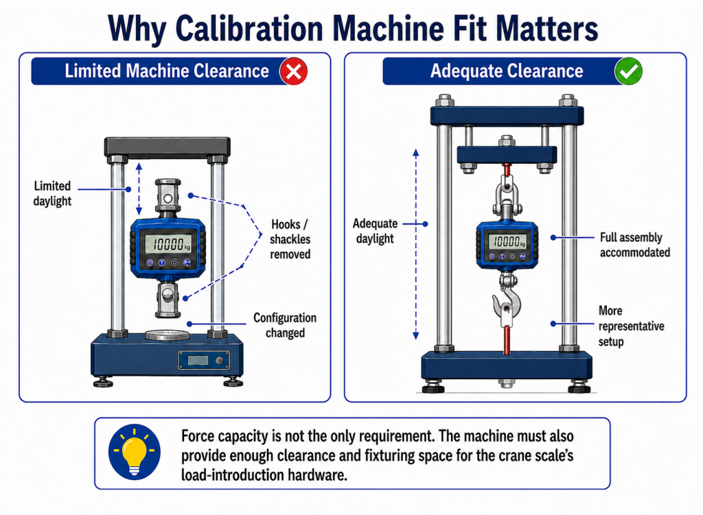
Force capacity is usually the first specification considered when selecting a machine for crane scale calibration.
It is not the only one.
Crane scales can be physically large, particularly after the upper shackle and lower hook are installed.
A calibration laboratory may have a machine capable of generating the required force but still lack sufficient:
- vertical daylight,
- usable stroke,
- space between loading points,
- fixture clearance,
- or room for the crane scale to align naturally.
When space is limited, the laboratory may be forced to remove the customer’s normal shackle, hook, or both simply to fit the instrument into the machine.
That can substantially change the calibration configuration.
Force capacity does not equal physical capability
Consider a calibration machine rated to a very high force but designed primarily for compact load cells.
It may have relatively little distance between the upper and lower loading points.
A crane scale may fit only after replacing a large hook and shackle with short rigid adapters.
The calibration can still provide useful force-response information, but the setup no longer represents the complete field configuration as closely as a machine with adequate clearance could.
Purpose-built force calibration systems
At Metrioc, our force calibration systems have been developed specifically around force calibration applications, including the need to accommodate physically large instruments.
For many crane scales, this allows the calibration setup to retain the scale’s hooks and shackles—or to use representative load-introduction hardware—rather than removing those components simply because of machine-clearance limitations.
This is an important distinction:
A calibration machine should have sufficient force capacity and sufficient physical space for the instrument and the required loading hardware.
Preloading, Seating, and Repeatability
Mechanical interfaces do not always return to exactly the same position each time a crane scale is unloaded.
A shackle pin may settle against a slightly different portion of an eye. A hook may rotate. Small clearances can be taken up differently as force increases.
For that reason, an initial preload or preconditioning sequence can be useful before formal calibration measurements begin, depending on the calibration procedure being used.
Preloading can help:
- seat mechanical connections,
- take up clearance,
- stabilize contact surfaces,
- settle the load train,
- and reveal obvious setup movement before calibration data are recorded.
Repeatability is also important.
If repeated applications of the same nominal force produce noticeably different indications, the cause may not necessarily be the electronics alone. Mechanical seating, changing alignment, pin movement, friction, or attachment geometry may also contribute.
A technically sound calibration setup therefore aims not only for axial loading but also for repeatable load introduction.
Check Zero Behavior Before and During Calibration
Zero is another useful indicator of crane-scale condition.
Before calibration, the laboratory should allow the instrument to stabilize and observe whether the unloaded indication remains reasonably stable.
After applying and removing substantial force, the instrument’s return toward its unloaded indication can also provide useful information.
A changing zero may be associated with several possible causes, including:
- mechanical seating,
- residual stress,
- electronic drift,
- temperature effects,
- damaged hardware,
- or other characteristics of the instrument.
A zero shift does not by itself identify the cause, but it can be an important observation when evaluating the measurement behavior of the device.
Battery Condition and Electronic Readiness
Many digital crane scales are battery powered.
The battery may be rechargeable or replaceable, but in either case it should be in suitable operating condition before calibration begins.
A strain-gage-based sensing system requires electrical excitation and signal conditioning. However, it would be an oversimplification to say that every reduction in battery voltage directly produces a proportional change in crane-scale indication.
Modern electronic instruments may use regulated excitation, ratiometric analog-to-digital conversion, internal voltage monitoring, or other circuitry that reduces sensitivity to ordinary battery-voltage changes.
The exact behavior depends on the crane scale’s design.
For that reason, the most technically appropriate recommendation is straightforward:
Charge the crane scale fully, or install fresh batteries of the manufacturer’s specified type, before calibration.
This removes battery condition as an unnecessary variable and helps ensure that the instrument is tested under its intended electrical operating condition.
A weak battery may also lead to:
- low-battery warnings,
- intermittent operation,
- unstable display behavior,
- communication problems,
- or shutdown during calibration.
Calibration is not the ideal time to discover that the instrument can no longer maintain normal operation.
Allow the Crane Scale to Reach Laboratory Temperature
Crane scales are portable instruments and may arrive at a laboratory after being transported in very different environmental conditions.
An instrument may have spent hours in:
- a hot delivery vehicle,
- an unheated warehouse,
- an outdoor work site,
- or a cold shipping container.
Temperature affects strain-gage load cells and their associated electronics. International load-cell metrology requirements such as OIML R 60 treat temperature as an important influence quantity in evaluating load-cell performance.
For precision calibration, the crane scale should therefore be given sufficient time to stabilize in the laboratory environment before measurements are taken.
The appropriate stabilization time depends on factors such as instrument mass, construction, temperature difference, and manufacturer requirements.
The goal is not simply to measure the air temperature.
The goal is to allow the instrument itself to approach a stable thermal condition.
Inspect the Load Path Before Calibration
Before applying high force, the calibration setup should be examined carefully.
Items to consider include:
- the condition of shackles,
- pin installation,
- retaining devices,
- hooks,
- visible deformation,
- corrosion,
- loose hardware,
- damaged threads,
- excessive wear,
- and anything that could prevent proper alignment.
This inspection should not be confused with a formal lifting-device safety inspection unless the laboratory is specifically qualified and contracted to perform one.
Calibration and lifting-hardware inspection are different activities.
A calibration determines measurement performance under defined conditions. It does not automatically certify that a shackle, hook, or other lifting component is safe for continued lifting service.
If questionable hardware is identified, the issue should be addressed before applying a calibration force.
Static Calibration Is Not the Same as Dynamic Crane Loading
Another important distinction involves the type of force being applied.
Crane scales are often used in environments where the load is not perfectly static.
During real lifting operations, the instrument may experience:
- acceleration,
- deceleration,
- swinging,
- vibration,
- impact,
- sudden load transfer,
- or dynamic amplification.
A conventional force calibration is generally performed under controlled static or quasi-static loading.
ASTM E74-18(2026), the current active edition of ASTM E74, specifically addresses calibration of static force-measuring instruments and states that results from static calibration should not automatically be assumed valid for dynamic or high-speed force measurements.
That distinction is important for crane-scale users.
A crane scale can perform very well during static calibration and still display different behavior under rapidly changing or oscillating loading conditions.
Static calibration establishes the instrument’s response under the conditions of the calibration. It should not be interpreted as a complete characterization of every possible dynamic lifting condition.
Calibration Is Not the Same as Proof Testing
Crane-scale terminology can sometimes create another source of confusion: calibration and proof testing are not the same process.
Calibration
Calibration establishes the relationship between a known applied reference force and the indication or output of the crane scale.
The purpose is measurement traceability and characterization of measurement performance.
Proof testing
Proof testing typically involves applying a specified load to demonstrate that equipment or hardware can withstand that loading condition in accordance with an applicable requirement or procedure.
Its purpose is fundamentally different.
Applying a large force to a crane scale does not automatically constitute a calibration, and performing an accurate calibration does not automatically constitute proof testing or safety certification of lifting hardware.
The required service should therefore be clearly defined before the instrument is sent to a laboratory.
A Crane Scale’s Sensor Responds to Force—but Applications Often Need Mass
The mechanical calibration issues discussed above address how force is applied to the crane scale.
There is another important question:
What quantity does the user ultimately need?
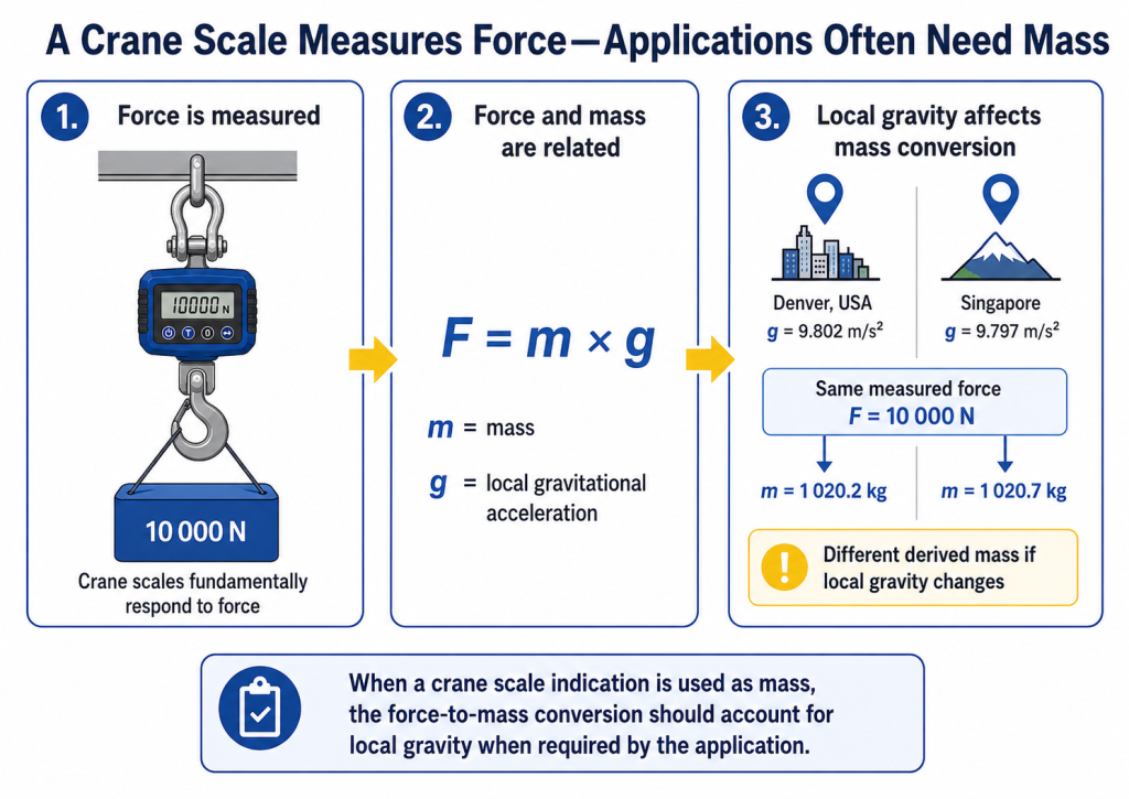
The sensing element inside a typical strain-gage crane scale responds to applied force. However, many crane scales display results using units commonly associated with mass, such as kilograms or pounds.
Force and mass are related by:
F = m × g
where:
- F is force,
- m is mass,
- and g is gravitational acceleration.
Rearranging the equation gives:
m = F / g
This distinction becomes important for portable weighing equipment because gravitational acceleration is not exactly the same everywhere on Earth.
NIST Handbook 44 explains the distinction between mass and weight and notes that gravitational acceleration varies by location. It also explains why a force-responsive weighing device can indicate differently when moved between locations with different local gravity unless the system is appropriately calibrated or adjusted.
That matters for equipment such as:
- crane scales,
- tension-link weighing systems,
- portable load-cell weighing systems,
- and other force-responsive portable weighing devices.
Local Gravity and Portable Crane Scales
A laboratory may apply a highly accurate known force to a crane scale.
But if the customer later uses that scale to infer mass at another geographic location, the force-to-mass relationship depends on the value of gravitational acceleration at the point of use.
Local gravity varies primarily with latitude and elevation, with smaller local variations caused by geology and terrain.
For example, the same measured force corresponds to slightly different calculated mass values at locations having different local gravitational acceleration:
m = F / g_local
This subject is especially important for portable crane scales because they may be calibrated or adjusted in one location and then used hundreds or thousands of kilometers away.
Metrioc discusses this issue in greater detail in our article Force vs. Mass in Portable Weighing: Why Local Gravity Matters.
For engineering evaluation, Metrioc also provides a Local Gravity Force-to-Mass Calculator, which estimates local gravity from location and elevation and calculates the corresponding mass from a measured force.
The calculator is an engineering and educational tool. Users should verify location data, calibration conditions, instrument settings, manufacturer requirements, and applicable regulatory requirements before relying on a result for regulated or commercial applications.
Commercial and Legal-for-Trade Applications Require Additional Consideration
A traceable force calibration and a mathematically correct force-to-mass conversion do not automatically establish that a crane scale is approved for commercial transactions.
In the United States, NIST Handbook 44 contains specifications, tolerances, and other technical requirements used by many state and local weights-and-measures jurisdictions for commercial weighing and measuring devices.
The 2026 edition is the current edition at the time of this article.
Therefore, when a crane scale is used for commercial or legal-for-trade weighing, the owner should determine:
- whether the device is suitable or approved for the intended application,
- which local or state weights-and-measures requirements apply,
- whether gravity adjustment or calibration at the place of use is required,
- and whether additional testing, sealing, inspection, or certification is necessary.
Force calibration, weighing calibration, and legal-for-trade approval are related subjects, but they are not interchangeable.
What Should You Send With a Crane Scale for Calibration?
Providing the laboratory with the right information and hardware can improve the quality and efficiency of the calibration.
Whenever practical, consider sending:
- The crane scale itself
- The normal upper shackle and pin
- The normal lower hook, swivel, or connection hardware
- Any proprietary adapters required for normal use
- The manufacturer’s operating instructions or model information
- A charged battery or fresh specified batteries
- Information about the units and ranges you actually use
- Any special calibration points required by your quality system
- Information about the intended application, particularly when the instrument is used for portable weighing or commercial weighing
If the normal shackle cannot be supplied, provide enough information for the laboratory to determine the manufacturer’s intended pin size and connection geometry.
That allows the laboratory to design or select a more representative adapter.
What Should a Good Crane Scale Calibration Laboratory Consider?
There is more to crane scale calibration than achieving the required force.
A capable laboratory should consider whether its setup can reproduce the intended measurement condition.
Important questions include:
- Can the calibration machine accommodate the complete crane scale assembly?
- Is there sufficient vertical clearance for the hooks and shackles?
- Is the load introduced along the intended measurement axis?
- Can the hardware self-align appropriately?
- Is the pin diameter representative of the manufacturer’s intended connection?
- Are side load, bending, and torsion minimized?
- Has the mechanical assembly been properly seated before data collection?
- Is the instrument thermally stable?
- Is the battery in proper operating condition?
- Is the calibration static, and is that appropriate for the customer’s application?
- Is the customer using the instrument to measure force, infer mass, or both?
These questions help connect the calibration result to the way the crane scale is actually used.
The Goal: Representative, Traceable Loading
The objective of crane scale calibration is not simply to suspend the instrument in a machine and apply force.
A meaningful calibration should establish the crane scale’s response under a controlled, traceable, and well-understood loading condition.
For crane scales, that loading condition is strongly connected to the mechanical load train.
Shackles, hooks, pins, alignment, fixture geometry, machine clearance, seating, temperature, and instrument readiness all deserve consideration.
In particular:
Use the normal shackles and hooks when practical.
If the original shackle is unavailable, reproduce the manufacturer’s intended pin diameter and loading geometry as closely as practical.
Keep the applied force aligned with the intended measurement axis.
Avoid introducing unnecessary side load, bending, and torque.
Use a calibration machine with enough physical clearance—not just enough force capacity.
Make sure the crane scale is thermally and electrically ready for calibration.
And when a force-responsive crane scale is being used to determine mass, remember that local gravity becomes part of the measurement problem.
The closer the calibration setup represents the instrument’s intended loading condition, the more useful the calibration result becomes to the people who depend on that instrument in the field.
Technical References
ASTM E74-18(2026)
Standard Practices for Calibration and Verification for Force-Measuring Instruments. ASTM International. Current active edition. Provides procedures and technical background for calibration of static force-measuring instruments and distinguishes static calibration from dynamic and high-speed force measurement.
ASTM E1012-19
Standard Practice for Verification of Testing Frame and Specimen Alignment Under Tensile and Compressive Axial Force Application. ASTM International. Provides technical background on axial alignment and the effects of bending introduced by misalignment.
OIML R 60:2021
Metrological Regulation for Load Cells. International Organization of Legal Metrology. Provides international metrological and technical requirements and performance-test principles for load cells, including influence quantities such as temperature.
NIST Handbook 44 — 2026 Edition
Specifications, Tolerances, and Other Technical Requirements for Weighing and Measuring Devices. National Institute of Standards and Technology. Provides technical and regulatory background for weighing devices, commercial weighing applications, and the distinction between mass and weight.
Technical note: The appropriate calibration configuration depends on the crane scale design, manufacturer’s instructions, intended use, customer requirements, applicable standards, and the calibration laboratory’s accredited scope. The considerations discussed here are intended to improve understanding of crane scale measurement and should not replace manufacturer requirements, lifting-equipment safety procedures, or applicable legal-metrology regulations.